Skip to content

Serielle Konsole UART2

Angeheftet Verschoben Hardware
  • Hier mal die Info's sammeln zur seriellen Konsole.

    • Baudrate: 1500000
    • Data bits: 8
    • Parity: N
    • Stop bits: 1

    Quelle: http://opensource.rock-chips.com/images/f/f9/RK3399_Linux_Debain_V1.1_Development_Guide170620.pdf
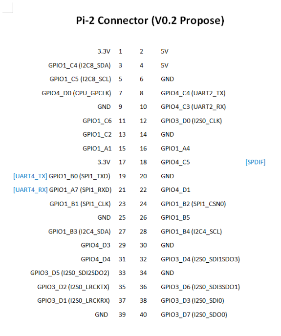
    0_1526196275573_Rockpro64 Pi-2 Connector ver0.2.png

    Es sieht so aus, das es auf den SOC's von Pine64 keinen separaten Steckplatz für die serielle Konsole gibt, so wie ich das von den Bananen her kenne. Man nutzt wohl direkt den UART2 Anschluss des Expansions Steckplatzes. Da hätten wir dann:

    Die rote Ader nicht anschließen!

    • Nr. 6 GND - schwarz
    • Nr. 8 UART2_TX - weiß
    • Nr. 10 UART2_ RX - grün

    Update vom 18. März 2019

    Seit dem Image 0.7.14 stört die Verbindung an Pin 10 das Booten des ROCKPro64, wenn dieser mit einem WiFi-Modul und einer PCIe-Karte bestückt ist. Das entfernen der Verbindung löst das Problem, man hat dann aber nur noch lesend Zugriff und kann keine Kommandos über die Konsole absetzen! Aber, das sollte das kleiner Problem sein. Die Entwickler sind informiert, keine Ahnung ob man das Fixen kann.
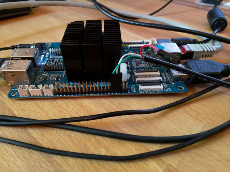
    0_1526803326819_konsole3.jpg

    Als Gedankenstütze, vom ROCK64 https://forum.pine64.org/showthread.php?tid=5008

    Damit sollten die vorhandenen USB-Adapter genauso wie bei den Bananen funktionieren!

    Achtung!

    Durch die schnelle Übertragungsrate kommt es bei verschiedenen Adaptern zu Darstellungsfehlern. Ein Adapter bei mir funktioniert nicht, fehlerhafte Darstellung. Mein billigster Adapter funktioniert, einwandfreie Darstellung.

    Also, wenn ihr Probleme habt, einfach mal einen anderen Adapter ausprobieren. Die anderen Angaben oben funktionieren!

    Tools zum Flashen

  • Ich habe ja einige Adapter ausprobiert, habe jetzt eine ordentliche Sammlung davon, aber habe jetzt einen gefunden der mir wohl alles anzeigt 😉

    Problem bei vielen Adaptern scheint die hohe Übertragungsrate zu sein. Wenn ihr als Ausgabe nur Müll bekommt, könnt ihr den Adapter direkt an die Seite legen, korrekter Anschluss vorausgesetzt!

    Einen Adapter den ich jetzt die ganze Zeit benutzt hatte, war folgender.

     Bus 003 Device 017: ID 10c4:ea60 Cygnal Integrated Products, Inc. CP210x UART Bridge / myAVR mySmartUSB light
    

    Ging, hatte aber das Problem das beim ersten Start die Ausgaben des U-Boots nicht vernünftig angezeigt werden. Wenn man mit den Platinen rumspielt, ist das sehr unvorteilhaft.

    Ok, nächster Versuch

    Bus 003 Device 016: ID 1a86:7523 QinHeng Electronics HL-340 USB-Serial adapter
    

    Und der zeigt jetzt auch den U-Boot vernünftig an. Benutzt wird folgendes Linux.

    rock64@rockpro64:~$ uname -a
    Linux rockpro64 4.4.126-rockchip-ayufan-239 #1 SMP Sun May 27 18:38:24 UTC 2018 aarch64 aarch64 aarch64 GNU/Linux
    

    Ausgabe

    channel 0 training pass!
    
    channel 1 training pass!
    
    change freq to 800MHz 1,0
    
    ch 0 ddrconfig = 0x101, ddrsize = 0x2020
    
    ch 1 ddrconfig = 0x101, ddrsize = 0x2020
    
    pmugrf_os_reg[2] = 0x3AA1FAA1, stride = 0xD
    
    OUT
    
    U-Boot SPL board init


    U-Boot SPL 2017.09-g03a332b (May 27 2018 - 18:34:10)
    
    booted from SD
    
    Trying to boot from MMC2
    
    NOTICE:  BL31: v1.3(debug):d98d16e
    
    NOTICE:  BL31: Built : 15:03:07, May 10 2018
    
    NOTICE:  BL31: Rockchip release version: v1.1
    
    INFO:    GICv3 with legacy support detected. ARM GICV3 driver initialized in EL3
    
    INFO:    Using opteed sec cpu_context!
    
    INFO:    boot cpu mask: 0
    
    INFO:    plat_rockchip_pmu_init(1151): pd status 3e
    
    INFO:    BL31: Initializing runtime services
    
    WARNING: No OPTEE provided by BL2 boot loader, Booting device without OPTEE initialization. SMC`s destined for OPTEE will return SMC_UNK
    
    ERROR:   Error initializing runtime service opteed_fast
    
    INFO:    BL31: Preparing for EL3 exit to normal world
    
    INFO:    Entry point address = 0x200000
    
    INFO:    SPSR = 0x3c9


    U-Boot 2017.09-g03a332b (May 27 2018 - 18:34:23 +0000), Build: jenkins-linux-build-rock-64-239
    

    So muss das sein. 🙂

    Mach ich selten, aber um es anderen etwas einfacher zu machen hier ein Amazon Link.
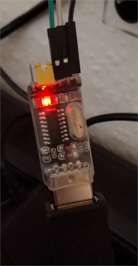
    0_1527938581023_Adapter_bearbeitet2.jpg

    Anschluss

    ROCKPro64 - Adapter

    • GND (6) - GND
    • TX (8) - RX
    • RX (10) - TX

    Zu Pin 10 bitte das Update im ersten Beitrag beachten!

    Die Brücke des Adapters steckt auf VCC / 3V3 und der Anschluss 5V ist frei. Das ist wohl ein Spannungsausgang, den man wahlweise auf 3V3 oder 5V schalten kann, den wir aber nicht benötigen!

    Die Einstellungen der seriellen Schnittstelle findet ihr im Eingangsthread.

    Ihr könnt natürlich, wenn ihr euch einen ROCKPro64 bestellt, direkt einen USB-Adapter mitbestellen!
    https://www.pine64.org/?product=padi-serial-console
    Ich setze mal voraus, das der funktioniert.

  • @FrankM
    Der anschluss 10 RX auf dem Rockpro64 V2.1 und warscheinlich auch anderen da das auf deiner Seite irgendwo erwähnt wurde muss beim booten frei sein.

    Es sieht so aus als ob der Prozessor darüber Spannung bekommt da der TX pin vom adapter "high" gezogen wird da scheint ein fehler in dem Layout oder Prozessor zu sein so das eine versorgung durch diesen pin auch "Rückwärts" funktioniert.

    Sehen kann man das wenn man GND und den pin 10 belegt, Spannung auf das Bord gibt und dann wieder trennt. Danach bleibt die Power LED leicht am glimmen. Nur anstecken des Serial converters reicht da nicht, dabei leuchtet die LED nicht auf. Außerdem geht das auch nur mit 5V Logic Level sonst kommt nicht genug an der LED an um es optisch zu erfassen das müsste man dann Messen, ist aber in jedem fall so nicht richtig.

    Sven

  • Ich mache das seit dem ersten Tag so, noch nie Probleme mit gehabt.

    Das mit der Rückspannung ist mir auch schon aufgefallen.

  • @tux_on_tour

    Hallo Sven,

    ich muss mich zu dem Thema noch mal äußern.

    Du hattest Recht! 👏

    Seit dem Image 0.7.14 (wifi & pcie) hatte ich das Problem das der ROCKPro64 nicht mehr booten möchte. Ein entfernen von Pin 10 löste das Problem.

    Vielen Dank nachträglich!!

    Nachteil, man kann von der Konsole aus nichts mehr machen!

    Ich werde das in meinen Anleitungen entsprechend ändern!

  • Es gibt Berichte im IRC, das es bei einigen auch mit der Verbindung zu Pin 10 geht. Vielleicht auch abhängig vom Adapter!? Im Zweifel einfach mal ausprobieren.

  • @FrankM
    Hallo, ich bin noch ganz unerfahren mit Pi's.
    Wenn ich jetzt eine Physische verbindung mit einer USB-TTL UART Konsole habe,
    wie stelle ich da eine Verbindung her?
    Ich habe Linux auch auf meinem Rechner drauf und bin nicht ganz begriffstuzig, was Konsolen angeht.
    Vielen Dank

    Cri

  • Ich verweise mal auf einen Artikel auf einer Webseite von mir, der Einsteiger Niveau hat.
    https://frank-mankel.de/wichtig/serielle-konsole

    Wenn es dann noch Probleme gibt, einfach fragen.

    Und beachte bitte, das wir hier nicht über PIs schreiben, sondern über ROCKPros. Da könnte es kleine Unterschiede geben. https://www.raspberrypi.org/documentation/configuration/uart.md

  • Mainline 5.11.x

    Images
    1
    0 Stimmen
    1 Beiträge
    220 Aufrufe
    Niemand hat geantwortet
  • Serielle Konsole UART2 (2)

    Angeheftet Hardware
    1
    0 Stimmen
    1 Beiträge
    212 Aufrufe
    Niemand hat geantwortet
  • Armbian 5.4.0-rc1

    Armbian
    5
    0 Stimmen
    5 Beiträge
    348 Aufrufe
    FrankMF

    Gut, ich bin nicht der einzige, der ständig damit Probleme hat. @tkaiser auch 😉

    1036201d-a4b2-47be-a618-36003c07e0ce-grafik.png

  • Der 3. ROCKPro64

    ROCKPro64
    3
    0 Stimmen
    3 Beiträge
    914 Aufrufe
    FrankMF

    Nachdem ich jetzt mein NAS neu gemacht habe, schauen wir mal, was die Chinesen geliefert haben. Bestellt hatte ich

    ROCKPro64 v2.1 2GB RAM Kühlkörper Netzteil 3A USB-Adapter für eMMC-Modul

    Endlich habe ich mal an den USB-Adapter für das eMMC-Modul gedacht 🙂

    0_1540029624802_IMG_20181020_115348_ergebnis.jpg

    Was ist mir aufgefallen? Das Versionsdatum ist neu (siehe oben) Die PCIe NVMe Karte ist neu

    Bei der PCIe NVMe Karte liegt eine Abstandshülse aus Messing und eine winzig kleine Schraube bei. Damit bekomme ich aber nicht die NVMe-SSD befestigt. Ich habe dann gemurkst 😉 Da sollte Pine64 unbedingt nachbessern!

    So sieht das dann zusammengebaut aus.

    0_1540029756582_IMG_20181020_115425_ergebnis.jpg

    0_1540029767082_IMG_20181020_115438_ergebnis.jpg

    Da ich ein paarmal gelesen hatte, das Leute Probleme mit dem PCIe NVMe Adapter hatten, direkt als erstes mal ein Test ob das reibungslos funktioniert.

    Sys rock64@rockpro64:/mnt$ uname -a Linux rockpro64 4.4.132-1075-rockchip-ayufan-ga83beded8524 #1 SMP Thu Jul 26 08:22:22 UTC 2018 aarch64 aarch64 aarch64 GNU/Linux lspci rock64@rockpro64:/mnt$ sudo lspci -vvv [sudo] password for rock64: 00:00.0 PCI bridge: Rockchip Inc. RK3399 PCI Express Root Port Device 0100 (prog-if 00 [Normal decode]) Control: I/O- Mem+ BusMaster+ SpecCycle- MemWINV- VGASnoop- ParErr- Stepping- SERR- FastB2B- DisINTx+ Status: Cap+ 66MHz- UDF- FastB2B- ParErr- DEVSEL=fast >TAbort+ <TAbort+ <MAbort+ >SERR+ <PERR+ INTx- Latency: 0 Interrupt: pin A routed to IRQ 238 Bus: primary=00, secondary=01, subordinate=01, sec-latency=0 I/O behind bridge: 00000000-00000fff Memory behind bridge: fa000000-fa0fffff Prefetchable memory behind bridge: 00000000-000fffff Secondary status: 66MHz- FastB2B- ParErr- DEVSEL=fast >TAbort- <TAbort- <MAbort- <SERR- <PERR- BridgeCtl: Parity- SERR- NoISA- VGA- MAbort- >Reset- FastB2B- PriDiscTmr- SecDiscTmr- DiscTmrStat- DiscTmrSERREn- Capabilities: [80] Power Management version 3 Flags: PMEClk- DSI- D1+ D2- AuxCurrent=0mA PME(D0+,D1+,D2-,D3hot+,D3cold-) Status: D0 NoSoftRst+ PME-Enable- DSel=0 DScale=0 PME+ Capabilities: [90] MSI: Enable+ Count=1/1 Maskable+ 64bit+ Address: 00000000fee30040 Data: 0000 Masking: 00000000 Pending: 00000000 Capabilities: [b0] MSI-X: Enable- Count=1 Masked- Vector table: BAR=0 offset=00000000 PBA: BAR=0 offset=00000008 Capabilities: [c0] Express (v2) Root Port (Slot+), MSI 00 DevCap: MaxPayload 256 bytes, PhantFunc 0 ExtTag- RBE+ DevCtl: Report errors: Correctable+ Non-Fatal+ Fatal+ Unsupported+ RlxdOrd+ ExtTag- PhantFunc- AuxPwr- NoSnoop+ MaxPayload 128 bytes, MaxReadReq 512 bytes DevSta: CorrErr- UncorrErr- FatalErr- UnsuppReq- AuxPwr- TransPend- LnkCap: Port #0, Speed 5GT/s, Width x4, ASPM L1, Exit Latency L0s <256ns, L1 <8us ClockPM- Surprise- LLActRep- BwNot+ ASPMOptComp+ LnkCtl: ASPM L1 Enabled; RCB 64 bytes Disabled- CommClk- ExtSynch- ClockPM- AutWidDis- BWInt+ AutBWInt+ LnkSta: Speed 5GT/s, Width x4, TrErr- Train- SlotClk- DLActive- BWMgmt- ABWMgmt- SltCap: AttnBtn- PwrCtrl- MRL- AttnInd- PwrInd- HotPlug- Surprise- Slot #0, PowerLimit 0.000W; Interlock- NoCompl- SltCtl: Enable: AttnBtn- PwrFlt- MRL- PresDet- CmdCplt- HPIrq- LinkChg- Control: AttnInd Off, PwrInd Off, Power+ Interlock- SltSta: Status: AttnBtn- PowerFlt- MRL+ CmdCplt- PresDet- Interlock- Changed: MRL- PresDet- LinkState- RootCtl: ErrCorrectable- ErrNon-Fatal- ErrFatal- PMEIntEna+ CRSVisible- RootCap: CRSVisible- RootSta: PME ReqID 0000, PMEStatus- PMEPending- DevCap2: Completion Timeout: Range B, TimeoutDis+, LTR+, OBFF Via message ARIFwd+ DevCtl2: Completion Timeout: 50us to 50ms, TimeoutDis-, LTR-, OBFF Disabled ARIFwd- LnkCtl2: Target Link Speed: 5GT/s, EnterCompliance- SpeedDis- Transmit Margin: Normal Operating Range, EnterModifiedCompliance- ComplianceSOS- Compliance De-emphasis: -6dB LnkSta2: Current De-emphasis Level: -6dB, EqualizationComplete-, EqualizationPhase1- EqualizationPhase2-, EqualizationPhase3-, LinkEqualizationRequest- Capabilities: [100 v2] Advanced Error Reporting UESta: DLP- SDES- TLP- FCP- CmpltTO- CmpltAbrt- UnxCmplt- RxOF- MalfTLP- ECRC- UnsupReq- ACSViol- UEMsk: DLP- SDES- TLP- FCP- CmpltTO- CmpltAbrt- UnxCmplt- RxOF- MalfTLP- ECRC- UnsupReq- ACSViol- UESvrt: DLP+ SDES+ TLP- FCP+ CmpltTO- CmpltAbrt- UnxCmplt- RxOF+ MalfTLP+ ECRC- UnsupReq- ACSViol- CESta: RxErr- BadTLP- BadDLLP- Rollover- Timeout- NonFatalErr- CEMsk: RxErr- BadTLP- BadDLLP- Rollover- Timeout- NonFatalErr+ AERCap: First Error Pointer: 00, GenCap+ CGenEn- ChkCap+ ChkEn- Capabilities: [274 v1] Transaction Processing Hints Interrupt vector mode supported Device specific mode supported Steering table in TPH capability structure Kernel driver in use: pcieport 01:00.0 Non-Volatile memory controller: Samsung Electronics Co Ltd NVMe SSD Controller SM961/PM961 (prog-if 02 [NVM Express]) Subsystem: Samsung Electronics Co Ltd NVMe SSD Controller SM961/PM961 Control: I/O- Mem+ BusMaster+ SpecCycle- MemWINV- VGASnoop- ParErr- Stepping- SERR- FastB2B- DisINTx+ Status: Cap+ 66MHz- UDF- FastB2B- ParErr- DEVSEL=fast >TAbort- <TAbort- <MAbort- >SERR- <PERR- INTx- Latency: 0 Interrupt: pin A routed to IRQ 237 Region 0: Memory at fa000000 (64-bit, non-prefetchable) [size=16K] Capabilities: [40] Power Management version 3 Flags: PMEClk- DSI- D1- D2- AuxCurrent=0mA PME(D0-,D1-,D2-,D3hot-,D3cold-) Status: D0 NoSoftRst+ PME-Enable- DSel=0 DScale=0 PME- Capabilities: [50] MSI: Enable- Count=1/32 Maskable- 64bit+ Address: 0000000000000000 Data: 0000 Capabilities: [70] Express (v2) Endpoint, MSI 00 DevCap: MaxPayload 256 bytes, PhantFunc 0, Latency L0s unlimited, L1 unlimited ExtTag- AttnBtn- AttnInd- PwrInd- RBE+ FLReset+ SlotPowerLimit 0.000W DevCtl: Report errors: Correctable- Non-Fatal- Fatal- Unsupported- RlxdOrd+ ExtTag- PhantFunc- AuxPwr- NoSnoop+ FLReset- MaxPayload 128 bytes, MaxReadReq 512 bytes DevSta: CorrErr- UncorrErr- FatalErr- UnsuppReq- AuxPwr+ TransPend- LnkCap: Port #0, Speed 8GT/s, Width x4, ASPM L1, Exit Latency L0s unlimited, L1 <64us ClockPM+ Surprise- LLActRep- BwNot- ASPMOptComp+ LnkCtl: ASPM L1 Enabled; RCB 64 bytes Disabled- CommClk- ExtSynch- ClockPM+ AutWidDis- BWInt- AutBWInt- LnkSta: Speed 5GT/s, Width x4, TrErr- Train- SlotClk+ DLActive- BWMgmt- ABWMgmt- DevCap2: Completion Timeout: Range ABCD, TimeoutDis+, LTR+, OBFF Not Supported DevCtl2: Completion Timeout: 50us to 50ms, TimeoutDis-, LTR-, OBFF Disabled LnkCtl2: Target Link Speed: 8GT/s, EnterCompliance- SpeedDis- Transmit Margin: Normal Operating Range, EnterModifiedCompliance- ComplianceSOS- Compliance De-emphasis: -6dB LnkSta2: Current De-emphasis Level: -6dB, EqualizationComplete-, EqualizationPhase1- EqualizationPhase2-, EqualizationPhase3-, LinkEqualizationRequest- Capabilities: [b0] MSI-X: Enable+ Count=8 Masked- Vector table: BAR=0 offset=00003000 PBA: BAR=0 offset=00002000 Capabilities: [100 v2] Advanced Error Reporting UESta: DLP- SDES- TLP- FCP- CmpltTO- CmpltAbrt- UnxCmplt- RxOF- MalfTLP- ECRC- UnsupReq- ACSViol- UEMsk: DLP- SDES- TLP- FCP- CmpltTO- CmpltAbrt- UnxCmplt- RxOF- MalfTLP- ECRC- UnsupReq- ACSViol- UESvrt: DLP+ SDES+ TLP- FCP+ CmpltTO- CmpltAbrt- UnxCmplt- RxOF+ MalfTLP+ ECRC- UnsupReq- ACSViol- CESta: RxErr- BadTLP- BadDLLP- Rollover- Timeout- NonFatalErr- CEMsk: RxErr- BadTLP- BadDLLP- Rollover- Timeout- NonFatalErr+ AERCap: First Error Pointer: 00, GenCap+ CGenEn- ChkCap+ ChkEn- Capabilities: [148 v1] Device Serial Number 00-00-00-00-00-00-00-00 Capabilities: [158 v1] Power Budgeting <?> Capabilities: [168 v1] #19 Capabilities: [188 v1] Latency Tolerance Reporting Max snoop latency: 0ns Max no snoop latency: 0ns Capabilities: [190 v1] L1 PM Substates L1SubCap: PCI-PM_L1.2+ PCI-PM_L1.1+ ASPM_L1.2+ ASPM_L1.1+ L1_PM_Substates+ PortCommonModeRestoreTime=10us PortTPowerOnTime=10us L1SubCtl1: PCI-PM_L1.2- PCI-PM_L1.1- ASPM_L1.2- ASPM_L1.1- T_CommonMode=0us LTR1.2_Threshold=0ns L1SubCtl2: T_PwrOn=10us Kernel driver in use: nvme

    Da sieht alles gut aus. x4 alles Bestens!

    iozone rock64@rockpro64:/mnt$ sudo iozone -e -I -a -s 100M -r 4k -r 16k -r 512k -r 1024k -r 16384k -i 0 -i 1 -i 2 Iozone: Performance Test of File I/O Version $Revision: 3.429 $ Compiled for 64 bit mode. Build: linux Contributors:William Norcott, Don Capps, Isom Crawford, Kirby Collins Al Slater, Scott Rhine, Mike Wisner, Ken Goss Steve Landherr, Brad Smith, Mark Kelly, Dr. Alain CYR, Randy Dunlap, Mark Montague, Dan Million, Gavin Brebner, Jean-Marc Zucconi, Jeff Blomberg, Benny Halevy, Dave Boone, Erik Habbinga, Kris Strecker, Walter Wong, Joshua Root, Fabrice Bacchella, Zhenghua Xue, Qin Li, Darren Sawyer, Vangel Bojaxhi, Ben England, Vikentsi Lapa. Run began: Sat Oct 20 10:08:28 2018 Include fsync in write timing O_DIRECT feature enabled Auto Mode File size set to 102400 kB Record Size 4 kB Record Size 16 kB Record Size 512 kB Record Size 1024 kB Record Size 16384 kB Command line used: iozone -e -I -a -s 100M -r 4k -r 16k -r 512k -r 1024k -r 16384k -i 0 -i 1 -i 2 Output is in kBytes/sec Time Resolution = 0.000001 seconds. Processor cache size set to 1024 kBytes. Processor cache line size set to 32 bytes. File stride size set to 17 * record size. random random bkwd record stride kB reclen write rewrite read reread read write read rewrite read fwrite frewrite fread freread 102400 4 63896 108269 91858 95309 32845 73173 102400 16 123393 236653 273766 275807 118450 199130 102400 512 471775 570571 484612 496942 441345 575817 102400 1024 544229 642558 508895 511834 486506 647765 102400 16384 1044520 1100322 1069825 1092146 1089301 1086757 iozone test complete.

    Das sieht nicht optimal aus, schau ich mir später an. Das hier soll nur ein kurzer Test sein ob das Board rennt 🙂

    Nachdem ich mittlerweile zwei ROCKPro64 im "produktiven" Einsatz habe, war es immer sehr mühsam mal eben was zu testen. Man will die anderen ja nicht immer ausmachen, dran rumhantieren usw. Deswegen jetzt der dritte, der im Moment dann die Rolle des Testkandidaten einnimmt. Ab sofort kann ich wieder nach Lust und Laune, neue Images testen usw.

  • ROCKPro64 - Stromverbrauch

    Hardware
    1
    0 Stimmen
    1 Beiträge
    781 Aufrufe
    Niemand hat geantwortet
  • ROCKPro64 - kein WLan-Modul möglich?

    ROCKPro64
    4
    0 Stimmen
    4 Beiträge
    2k Aufrufe
    FrankMF

    Heute, 5 Monate später, kann ich bestätigen das WLan möglich ist 🙂 Getestet auf einem ROCKPro64 v2.1 mit 2GB RAM.

    Eine Vorabversion von Recalbox machte es das erste Mal für mich möglich das WLan zu benutzen. Bericht

    Und PCIe ist abgeschaltet im dts File.

    pcie-phy { compatible = "rockchip,rk3399-pcie-phy"; #phy-cells = <0x0>; rockchip,grf = <0x15>; clocks = <0x8 0x8a>; clock-names = "refclk"; resets = <0x8 0x87>; reset-names = "phy"; status = "disabled"; phandle = <0x8b>; }; pcie@f8000000 { compatible = "rockchip,rk3399-pcie"; #address-cells = <0x3>; #size-cells = <0x2>; aspm-no-l0s; clocks = <0x8 0xc5 0x8 0xc4 0x8 0x147 0x8 0xa0>; clock-names = "aclk", "aclk-perf", "hclk", "pm"; bus-range = <0x0 0x1f>; max-link-speed = <0x2>; linux,pci-domain = <0x0>; msi-map = <0x0 0x89 0x0 0x1000>; interrupts = <0x0 0x31 0x4 0x0 0x0 0x32 0x4 0x0 0x0 0x33 0x4 0x0>; interrupt-names = "sys", "legacy", "client"; #interrupt-cells = <0x1>; interrupt-map-mask = <0x0 0x0 0x0 0x7>; interrupt-map = <0x0 0x0 0x0 0x1 0x8a 0x0 0x0 0x0 0x0 0x2 0x8a 0x1 0x0 0x0 0x0 0x3 0x8a 0x2 0x0 0x0 0x0 0x4 0x8a 0x3>; phys = <0x8b>; phy-names = "pcie-phy"; ranges = <0x83000000 0x0 0xfa000000 0x0 0xfa000000 0x0 0x1e00000 0x81000000 0x0 0xfbe00000 0x0 0xfbe00000 0x0 0x100000>; reg = <0x0 0xf8000000 0x0 0x2000000 0x0 0xfd000000 0x0 0x1000000>; reg-names = "axi-base", "apb-base"; resets = <0x8 0x82 0x8 0x83 0x8 0x84 0x8 0x85 0x8 0x86 0x8 0x81 0x8 0x80>; reset-names = "core", "mgmt", "mgmt-sticky", "pipe", "pm", "pclk", "aclk"; status = "disabled";

    Also bleibt weiterhin ungeklärt, ob auch beides zusammen möglich ist. Also gleichzeitig das WLan-Modul und eine PCIe Karte.

  • OMV Images

    ROCKPro64
    3
    0 Stimmen
    3 Beiträge
    837 Aufrufe
    FrankMF

    Kurzes Update

    https://github.com/ayufan-rock64/linux-build/releases/download/0.8.0rc10/stretch-openmediavault-rockpro64-0.8.0rc10-1125-armhf.img.xz

    Startet 🙂 Incl. WiFi & PCIe NVMe SSD

    War aber nur ein ganz kurzer Test!!

  • Links

    Angeheftet Linux
    1
    0 Stimmen
    1 Beiträge
    763 Aufrufe
    Niemand hat geantwortet